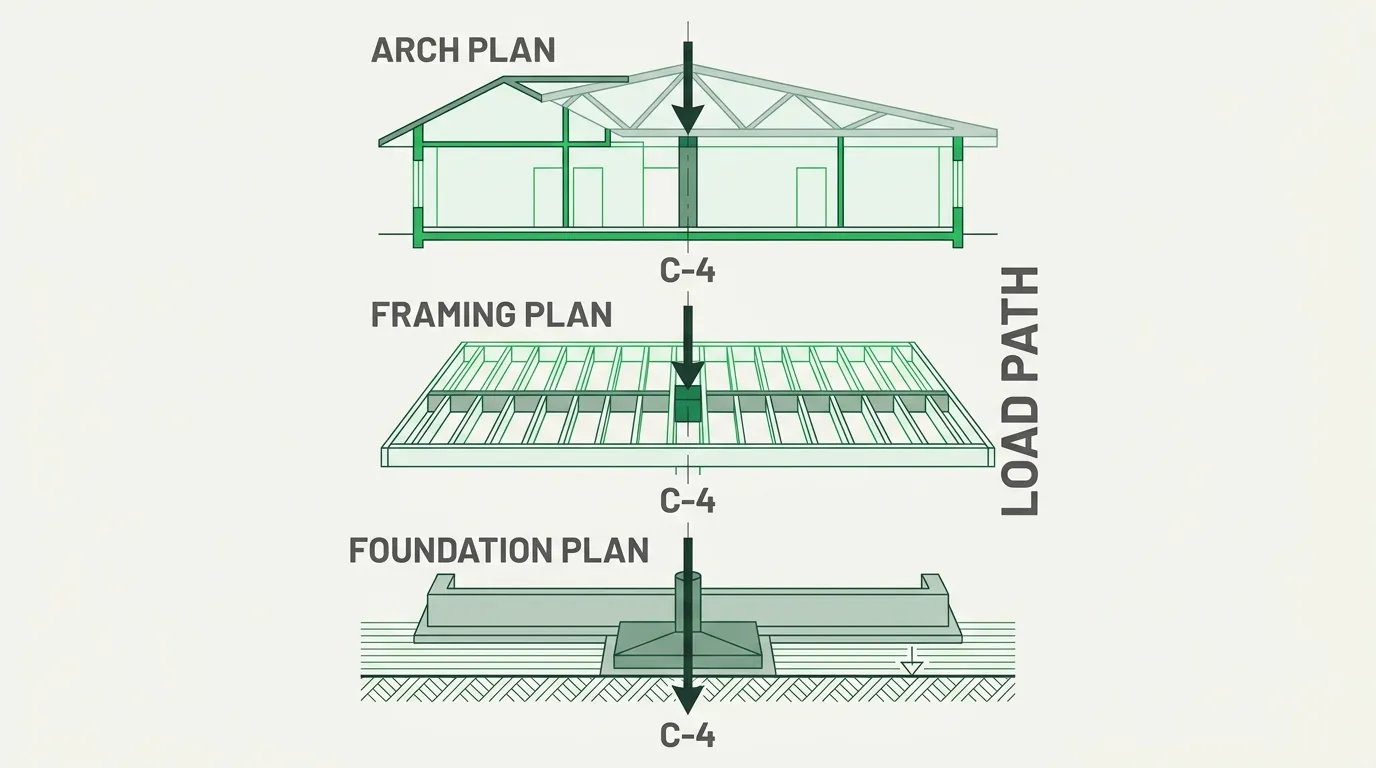
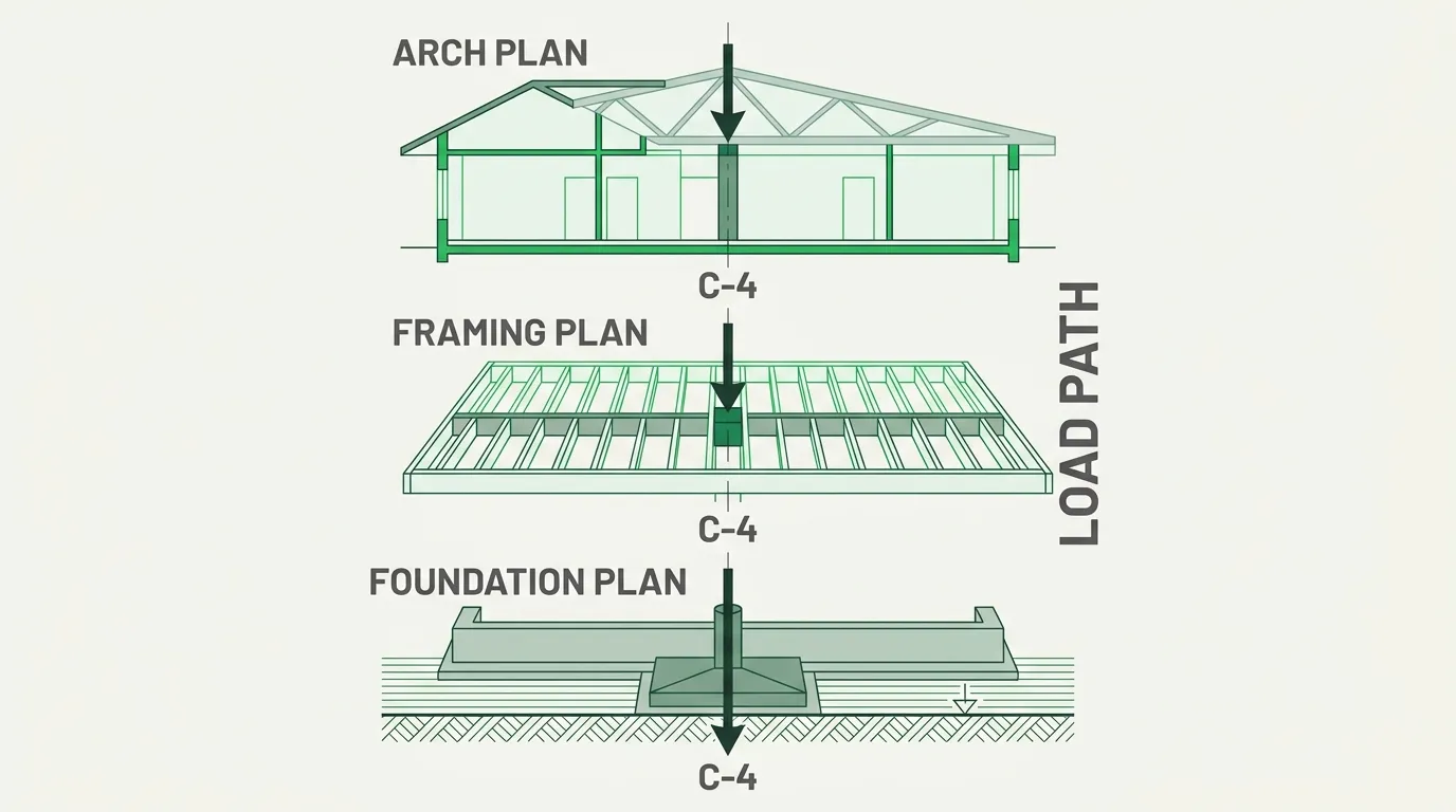
A building stands because force has a place to go. Every load (the weight of the floor above, the wind against the wall, the equipment on the roof) travels down a continuous path through slabs and beams and columns into the foundation and, finally, into the ground. Structural engineers call this the load path, and its first rule is unforgiving: it has to be continuous. A break anywhere is not a tolerance issue. It is the difference between a structure that carries its loads and one that doesn’t.
The load path is designed in three dimensions but drawn in two, across separate plans that must agree on every shared element. The architectural plan places a column. The framing plan frames to it. The foundation plan puts a footing under it. If those three drawings disagree about where that column is, even by the width of a gridline note, the load path they collectively describe is broken on paper, and someone has to catch it before it is broken in concrete.
That someone is the engineer, working by hand, column by column. We think the checking is a job for a spatial model, and the judgment is a job for the engineer, and that the two should not be the same task.
Three plans, one column, and the gap between them
Take one column. On the architectural plan it sits on gridline C-4. On the framing plan, the beams that deliver load to it are drawn to a point that, after a late architectural change nobody re-coordinated, has shifted six inches. On the foundation plan, the footing was sized and placed to the original location. Three drawings, one column, and a load path that no longer lands where its support was built.
Nothing here is dramatic on any single sheet. Each plan is internally correct. The architect moved the column for a good reason. The framing was drawn before the move. The foundation followed the framing. The break exists only in the relationship between the three plans, and no single plan shows a relationship. A column that isn’t vertically continuous from foundation upward is a serious structural risk, and it cannot be quietly fixed once concrete is placed; catching it late means demolition, not adjustment.
Coordination gaps between structural, architectural, and MEP plans are among the most common sources of construction rework, and structural rework is the most expensive and highest-liability kind there is. When a load-path discontinuity survives to the field, it does not produce a clean change order. It produces a stop-work, an engineer on site, and a decision that has to be made under schedule pressure with concrete already poured.
Why load-path checking eats an engineer’s hours
Engineers validate load paths by doing exactly what the drawings force them to do: they open all three plans and check every column against every plan, one gridline at a time. It is careful, expert, and staggeringly manual. On a building with a hundred columns, it is a hundred cross-checks, each one a small act of holding two or three sheets in mind and confirming they agree.
This is precisely the work that gets compressed when the deadline moves. And it is precisely the work where a single missed discrepancy has an outsized cost. Design errors and omissions are the leading driver of rework, and rework and conflict resolution cost U.S. construction more than $177 billion a year (PlanGrid/FMI, 2018), with direct rework running 9% to 20% of total project cost (Becht). A load-path check is one of the highest-leverage reviews an engineer performs, and it is done with the crudest possible tooling: two windows open side by side and a trained eye moving between them.
The tragedy is that the check is fundamentally mechanical. Does the column on plan A exist, in the same place, on plans B and C? Does the footing under it carry the load framed to it? These are questions with definite answers that live entirely in the geometry. The engineer’s scarce, expensive judgment is being spent finding the discrepancy, when it should be spent deciding what to do about it.
A model that reads the plans as one structure
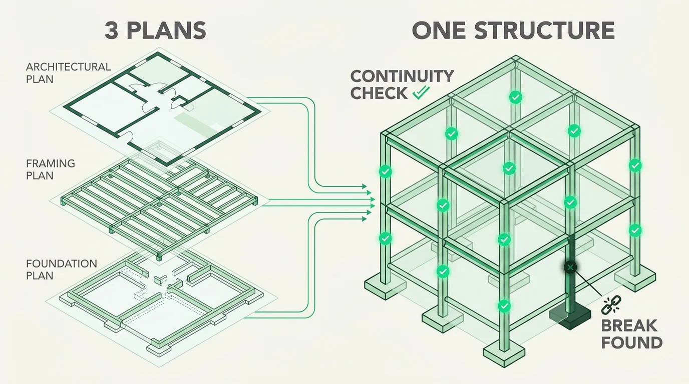
Reverse the projection. A set of 2D structural plans is a flattened description of a 3D structure. If a model can read the architectural plan, the framing plan, and the foundation plan and reconstruct the structure they collectively describe, then a column stops being three marks on three sheets and becomes one node in a connected structural graph. With a top, a bottom, a load coming in, and a support underneath.
Once the column is a single node, load-path continuity becomes a property a model can check directly. Does every column framed on the structural plan have a footing under it on the foundation plan? Does every column’s location agree across all three sheets? These are questions with definite answers that live entirely in the geometry, which is exactly what makes them the right target for a spatial model to surface at draft time, before the set is issued, before the footing is poured. It is the same class of spatial reasoning that reconstructs a building’s systems from the drawings that describe them; load-path validation is one query against that reconstructed model.
You cannot get here by overlaying PDFs, because overlay shows you pixels, not structure. It can’t tell you that two marks are the same column rather than two marks that happen to be near each other. And you cannot get here by pushing the plans into a spreadsheet, because a spreadsheet has no concept of space. Reconstructing the structure from 2D plans requires a model that natively understands geometry and topology together, and that spatial foundation, the ability to read a set as one connected object, is what Boon has built and what load-path validation would be built on.
Structural is where a spatial model earns its keep
Structural engineering is the discipline where the cost of a missed cross-sheet conflict is highest and the tooling to catch it is oldest. That combination is exactly where a spatial model creates the most value. Not by replacing the engineer’s judgment, but by doing the archaeology that judgment currently gets buried under.
And load-path validation is not a standalone product; it is one more query against the same connected model that powers takeoff, coordination, and clash detection. The model that can trace a column from foundation to roof can also count that column, price it, and check whether the mechanical run wants to occupy the same space. Every structural set Boon reads makes the underlying model better at recognizing how load paths are described, and where they tend to break, which is what would let a checker like this get sharper with every project.
The engineer decides whether a load path is sound. That is, and should remain, expert human judgment on the highest-liability work in the building. What the engineer should not have to do is find the broken column by hand, on the third pass, at 11 p.m. before issuance. A spatial model can hand them a list of every discontinuity in the set before they open the file, so their judgment goes to the decision, not the search.
A broken load path is the most expensive thing a structural set can hide. It should never make it to the field. Read the plans as one structure, and it doesn’t have to.